用 ESP-01S 和 RC522 打造 WiFi 门禁:UDP 通信 + 舵机控制实战
 0
0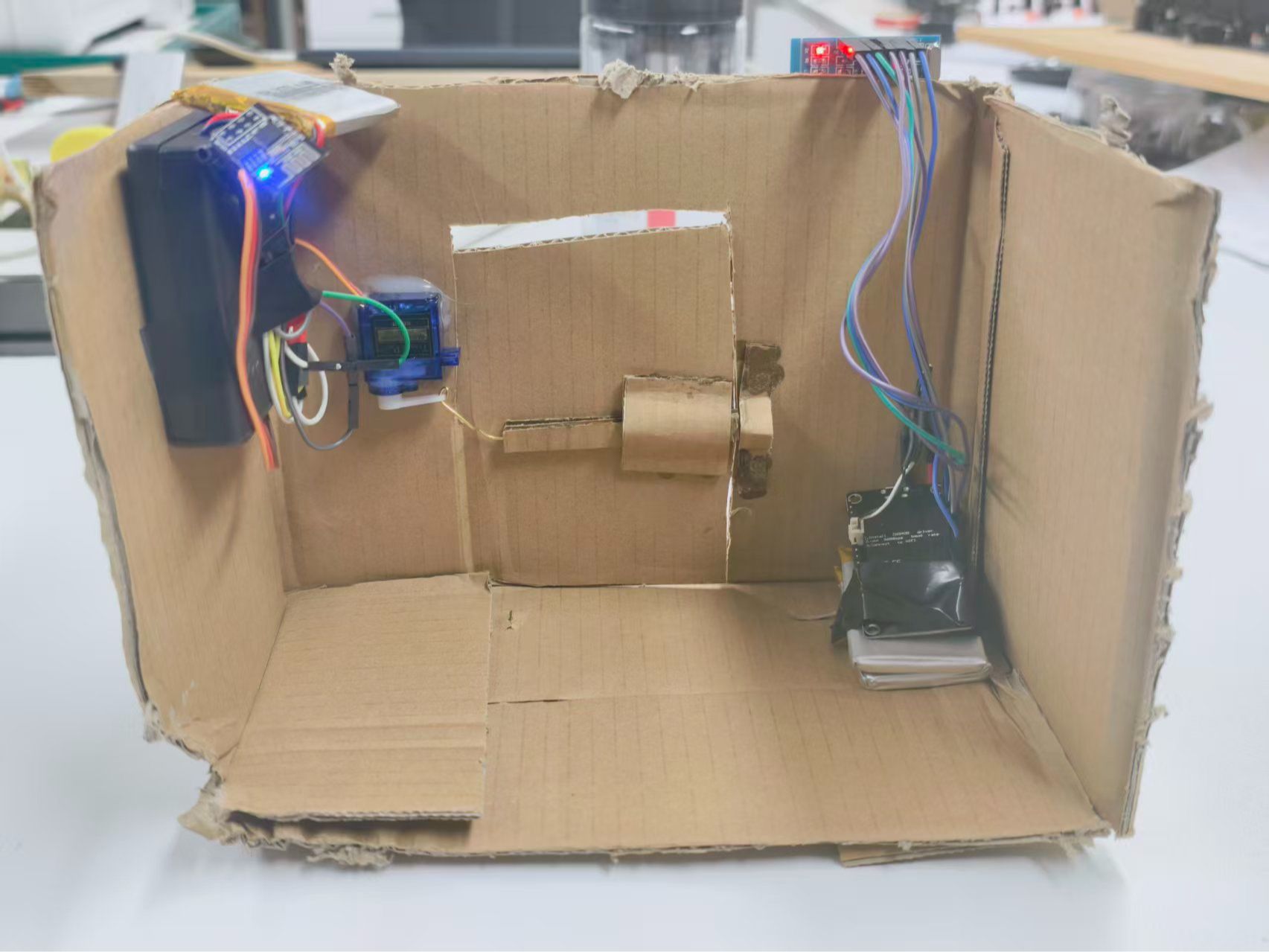
本文介绍如何基于 ESP-01S 与 ESP8266 实现局域网内的 UDP 通信,并结合 RC522 射频识别模块构建一个门禁系统。当 RC522 读取到白名单中的卡片 UID 时,系统将自动通过 UDP 协议向 ESP-01S 发送指令,驱动舵机完成开门操作。
准备工作:
材料:
材料名称
数量
备注
ESP8266
1
ESP-01s
1
SG90
1
RC522
1
锂电池块
2
电池盒
1
电池
4节
电工胶布
1卷
工具:
工具名称
数量
备注
烙铁
1
剥线钳
1
1
设置ESP8266下载地址


12
在Arduino IDE的开发板管理器中,添加ESP8266的下载源地址:http://arduino.esp8266.com/stable/package_esp8266com_index.json。
2
下载开发板


12
安装ESP8266开发板:
- 工具 → 开发板 → 开发板管理器 → 搜索
esp8266→ 安装
安装 MFRC522 库:
- 工具 → 管理库 → 搜索
MFRC522→ 安装 “MFRC522 by GithubCommunity”
3
esp01s烧录代码


123
这是ESP01s和烧录器的连接对应:
usb转ttl | esp01 |
3.3v | 3.3v |
GND | GND |
TX | RX |
RX | TX |
GND | GPIO0 |
// === ESP-01S: 舵机控制端 ===
#include <ESP8266WiFi.h>
#include <WiFiUdp.h>
#include <Servo.h>
const char* ssid = "vivoX200";
const char* password = "12345678";
WiFiUDP udp;
const int localPort = 8888;
Servo myservo;
const int SERVO_PIN = 2; // GPIO2
const int LOCK_ANGLE = 0;
const int UNLOCK_ANGLE = 180;
void setup() {
Serial.begin(115200);
myservo.attach(SERVO_PIN);
myservo.write(LOCK_ANGLE); // 默认上锁
WiFi.begin(ssid, password);
while (WiFi.status() != WL_CONNECTED) {
delay(500);
Serial.print(".");
}
Serial.println("\n ESP-01S 已联网");
Serial.print("IP: "); Serial.println(WiFi.localIP());
udp.begin(localPort);
Serial.println("监听 UDP 端口 8888...");
}
void loop() {
int packetSize = udp.parsePacket();
if (packetSize) {
char cmd[10];
int len = udp.read(cmd, 9);
cmd[len] = '\0';
Serial.print(" 收到指令: ");
Serial.println(cmd);
if (strcmp(cmd, "OPEN") == 0) {
myservo.write(UNLOCK_ANGLE);
delay(5000); // 保持 5 秒
myservo.write(LOCK_ANGLE);
Serial.println("门已重新上锁");
}
}
}
烧录步骤说明:
- 按照上表连接好线路,其中将烧录器的 GND 同时连接到 ESP-01S 的 GND 和 GPIO0,使模块进入下载模式。
- 完成代码烧录后,断开 GPIO0 与 GND 的连接。
- 拔掉烧录器并重新插入(或重新上电),此时 ESP-01S 将正常启动,并可通过串口查看打印信息。
- 请记录串口输出中的 IP 地址,后续 ESP8266 的通信将使用该 IP。
ESP-01s.ino
1.10KB
4
ESP-01s、舵机接线图


123
制作共地连接线:
取一根公对公杜邦线和一根母对母杜邦线,分别从中间剪断,使用剥线钳剥去两端的绝缘外皮,然后将对应导线拧在一起,形成一根可靠的接地(GND)连接线。
准备两个独立电源:
- 电源 A:输出 5V,用于驱动舵机。
- 电源 B:输出 3.3V ± 0.1V,用于为 ESP-01S 供电。
连接舵机:
- 舵机 红色线(VCC) → 接 5V 电源正极(+)
- 舵机 棕色或黑色线(GND) → 接 5V 电源负极(–)
连接 ESP-01S:
- ESP-01S VCC 引脚 → 接 3.3V 电源正极(+)
- ESP-01S GND 引脚 → 接 3.3V 电源负极(–)
关键步骤:共地(Common Ground)
使用一根杜邦线,将 5V 电源的负极(–) 与 3.3V 电源的负极(–) 连接起来,确保两个电源共用同一个参考地,这是信号正常通信的前提。
信号线连接:
- 舵机的 黄色或橙色线(信号线) → 接 ESP-01S 的 GPIO2 引脚
5
esp8266和RC522接线图


12
8266和RC522的引脚对应:
RC522引脚 | NodeMCU |
3.3v | 3.3v |
GND | GND |
RST | D3 |
SDA | D8 |
SCK | D5 |
MOSI | D7 |
MISO | D6 |
RC522 模块工作电压为 3.3V,需稳定供电。建议使用 3.3V 锂电池 为整体供电:
- 将锂电池的 正极 接至 8266的 3.3V 引脚
- 将锂电池的 负极 接至 8266的 GND 引脚
// NFC 门禁系统 - NodeMCU + RC522
#include <ESP8266WiFi.h>
#include <WiFiUdp.h>
#include <SPI.h>
#include <MFRC522.h>
#include <EEPROM.h>
// ====== Wi-Fi 配置 ======
const char* ssid = "名称";
const char* password = "密码";
// ====== UDP 目标 ======
const char* remoteIP = "192.168.190.236"; // 修改为自己的IP
const int remotePort = 8888;
WiFiUDP udp;
// ====== RC522 引脚 ======
#define SS_PIN 15 // D8
#define RST_PIN 2 // D4 (避免 GPIO0)
MFRC522 mfrc522(SS_PIN, RST_PIN);
// ====== 配置 ======
#define MAX_CARDS 20
#define UID_SIZE 4
const int EEPROM_RESERVED_SIZE = 512; // 必须 >= 实际使用
bool learningMode = false;
unsigned long learningStartTime = 0;
// =============================================================================
void setup() {
Serial.begin(115200);
delay(500);
Serial.println("\nNFC 门禁系统启动...");
WiFi.begin(ssid, password);
while (WiFi.status() != WL_CONNECTED) {
delay(500);
Serial.print(".");
}
Serial.println("\nWi-Fi 已连接");
Serial.print("本机 IP: ");
Serial.println(WiFi.localIP());
SPI.begin();
mfrc522.PCD_Init();
mfrc522.PCD_SetAntennaGain(mfrc522.RxGain_max);
EEPROM.begin(EEPROM_RESERVED_SIZE);
// 正确统计已授权卡数(基于 0xFF 判断空)
int count = 0;
for (int i = 0; i < MAX_CARDS; i++) {
bool isEmpty = true;
for (int j = 0; j < UID_SIZE; j++) {
if (EEPROM.read(i * UID_SIZE + j) != 0xFF) {
isEmpty = false;
break;
}
}
if (!isEmpty) count++;
}
Serial.printf("已授权卡片: %d / %d 张\n", count, MAX_CARDS);
learningMode = true;
learningStartTime = millis();
Serial.println("5 秒内刷卡可录入新卡!");
}
// =============================================================================
void loop() {
unsigned long now = millis();
if (learningMode && (now - learningStartTime > 5000)) {
learningMode = false;
int count = 0;
for (int i = 0; i < MAX_CARDS; i++) {
bool isEmpty = true;
for (int j = 0; j < UID_SIZE; j++) {
if (EEPROM.read(i * UID_SIZE + j) != 0xFF) {
isEmpty = false;
break;
}
}
if (!isEmpty) count++;
}
Serial.printf("当前授权卡: %d 张\n", count);
}
if (!mfrc522.PICC_IsNewCardPresent()) return;
if (!mfrc522.PICC_ReadCardSerial()) return;
if (mfrc522.uid.size != UID_SIZE) {
Serial.println("不支持的卡类型");
goto halt;
}
byte uid[UID_SIZE];
for (int i = 0; i < UID_SIZE; i++) uid[i] = mfrc522.uid.uidByte[i];
Serial.print("UID: ");
for (int i = 0; i < UID_SIZE; i++) {
Serial.printf("%02X", uid[i]);
if (i < UID_SIZE - 1) Serial.print(":");
}
if (learningMode) {
if (addCardToEEPROM(uid)) {
Serial.println(" 录入成功!");
} else {
Serial.println(" 已存在或存储已满");
}
} else {
if (isAuthorized(uid)) {
Serial.println(" 合法卡,开门!");
sendUDP("OPEN");
} else {
Serial.println(" 未授权卡");
}
}
halt:
mfrc522.PICC_HaltA();
mfrc522.PCD_StopCrypto1();
delay(500);
}
// =============================================================================
// 正确判断槽位是否为空(基于 0xFF)
bool isSlotEmpty(int slot) {
for (int j = 0; j < UID_SIZE; j++) {
if (EEPROM.read(slot * UID_SIZE + j) != 0xFF) {
return false;
}
}
return true;
}
// =============================================================================
bool isAuthorized(byte* uid) {
for (int i = 0; i < MAX_CARDS; i++) {
if (isSlotEmpty(i)) continue; // 跳过空槽
bool match = true;
for (int j = 0; j < UID_SIZE; j++) {
if (EEPROM.read(i * UID_SIZE + j) != uid[j]) {
match = false;
break;
}
}
if (match) return true;
}
return false;
}
bool addCardToEEPROM(byte* uid) {
if (isAuthorized(uid)) return false;
for (int i = 0; i < MAX_CARDS; i++) {
if (isSlotEmpty(i)) {
for (int j = 0; j < UID_SIZE; j++) {
EEPROM.write(i * UID_SIZE + j, uid[j]);
}
EEPROM.commit();
return true;
}
}
return false;
}
void sendUDP(const char* msg) {
udp.beginPacket(remoteIP, remotePort);
udp.write(msg);
udp.endPacket();
}
ESP8266.ino
5.28KB
6
最终


123
我用纸壳搭了个原型,实际应用时完全可以装到真正的门上——把控制模块(比如 ESP-01S 和电源)藏在门后,RC522 留在外面方便刷卡。
布线完成后,整个系统就准备好了:刷一张白名单里的卡,信号通过 UDP 发出去,另一边收到指令驱动舵机开门。
 0
0 0
0 0
0 qq空间
qq空间  微博
微博  复制链接
复制链接 更多相关项目
猜你喜欢
评论/提问(已发布 0 条)