Arduino 颜色选择器
发布时间: 2025-06-20 16:41:10 |  0
0 0
0 0
0 0
0
0Arduino
arduino
颜色选择
GUI
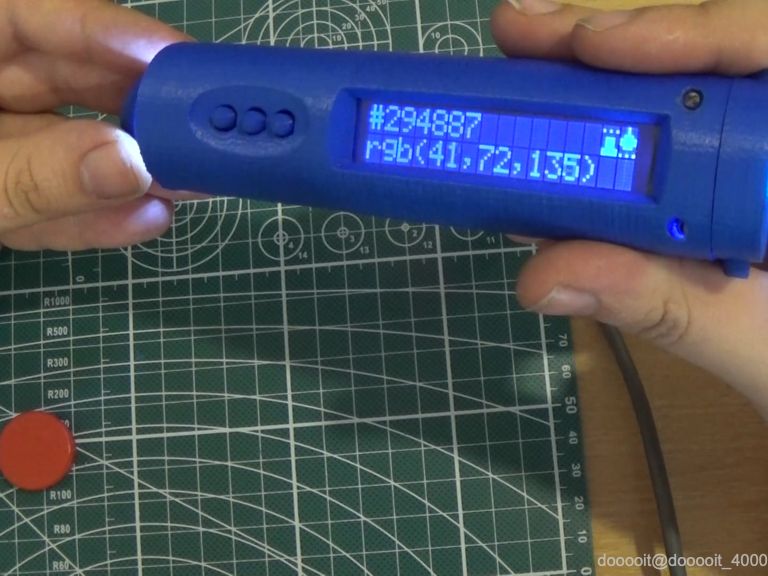
今天我想与大家分享的项目是 Arduino 颜色选择器,这是一种可以让您从现实生活中的物体中挑选任何颜色并以方便的方式显示它的设备,以便您可以在任何绘图软件、GUI Web 开发等中使用它!
1
零件清单

对于这个项目我们需要:
- DFRobot推出适用于 Arduino 的 TCS34725 RGB 颜色传感器
- DFRobot出品的I2C 16x2 Arduino LCD 带 RGB 字体显示
- DFRobot的DFRduino Pro Mini V1.3(8M3.3V328)
- 2 个 CR2032 电池盒
- 滑动开关
- RGB LED模块
- 电线
- 3x7厘米原型PCB
- 公头和母头排针
- 2x M2x20 螺钉和螺母
工具:
- 3D 打印机,如果您没有,您可以从 Shapeways 获取打印的外壳:单击此处
- 十字螺丝刀
- 烙铁
- 焊接
2
原理图

请参阅下面打开的视频的组装部分和示意图,了解如何将零件放置在 PCB 上。
使用上面提供的示意图进行正确接线。
3
设计并3D打印外壳

测量完零件后,我们就可以设计 3D 外壳并打印它了!
设计
这是我在 tinkercad 上的设计的链接:https://www.tinkercad.com/things/dG47Pr28uwx
上述案例的设计是为了完美适合上面列出的所有组件。
前部将容纳液晶屏和颜色传感器。
主 3x7 厘米 PCB 将容纳 DFFRduino Pro Mini、电池座和 3 个按钮,并将从内部拧在后部。
RGB LED 将位于后部的顶部内部。
电源开关将安装在背面的小孔中。
印刷
可在 Thingiverse 上获取可供打印的 3D 模型:https://www.thingiverse.com/thing :3223709
打印设置可能因打印机而异。
电池盖部分和前部需要支撑,因为前部具有内置距离器,以提供颜色传感器和样本之间的距离。
如果您没有 3D 打印机,您可以从 Shapeways 获取打印外壳:点击此处
集会
有关组装说明,请参阅开头提供的视频的组装部分。
FFFCA13JOYNTIEC.stl
135.43KB
FZHKVU5JOYNTIGJ.stl
182.50KB
FRUDEE1JOYNTIHF.stl
34.75KB
FJZCFOTJOYNTIIR.stl
24.11KB
FDYJDFVJOYNTIKW.stl
76.74KB
4
源代码

源代码可在 GitHub 上免费获取:https://github.com/alojzjakob/Arduino-Color-Picker
我们非常欢迎您改进代码,因为所提供的代码只是一个起点,但效果很好。
该项目使用这两个特定的库,因此请确保将它们添加到您的 Arduino IDE:
- https://github.com/bearwaterfall/DFRobot_LCD-master/tree/master
- https://github.com/DFRobot/DFRobot_TCS34725/raw/master/DFRobot_TCS34725.rar
#include <DFRobot_TCS34725.h>
#include <DFRobot_LCD.h>#define ledPin 12
#define redpin 3
#define greenpin 5
#define bluepin 6const int8_t button1Pin = 7; //1
const int8_t button2Pin = 8; //2
const int8_t button3Pin = 9; //3int8_t button1State = 0;
int8_t button2State = 0;
int8_t button3State = 0;#define ACTIVATED LOW// for a common anode LED, connect the common pin to +5V
// for common cathode, connect the common to ground
// set to false if using a common cathode LED
#define commonAnode true// our RGB -> eye-recognized gamma color
byte gammatable[256];DFRobot_LCD lcd(16,2);
DFRobot_TCS34725 tcs = DFRobot_TCS34725(0x50, TCS34725_GAIN_60X);bool ledEnabled=false;
int lightsMode=0;// make some custom characters:
byte light_on[8] = {
0b00100,
0b00100,
0b01110,
0b11111,
0b11111,
0b01110,
0b00000,
0b10101
};byte light_off[8] = {
0b00100,
0b00100,
0b01110,
0b10001,
0b10001,
0b01110,
0b00000,
0b00000
};byte rgb_on[8] = {
0b00000,
0b10101,
0b00000,
0b01110,
0b01110,
0b01110,
0b11111,
0b11111
};byte rgb_off[8] = {
0b00000,
0b00000,
0b00000,
0b01110,
0b01010,
0b01010,
0b10001,
0b11111
};void setup() { lcd.init();
// create a new character
lcd.customSymbol(0, light_on);
lcd.customSymbol(1, light_off);
lcd.customSymbol(2, rgb_on);
lcd.customSymbol(3, rgb_off); pinMode(ledPin, OUTPUT);
digitalWrite(ledPin, LOW); pinMode(button1Pin, INPUT);
pinMode(button2Pin, INPUT);
pinMode(button3Pin, INPUT);
digitalWrite(button1Pin, HIGH);
digitalWrite(button2Pin, HIGH);
digitalWrite(button3Pin, HIGH);
pinMode(redpin, OUTPUT);
pinMode(greenpin, OUTPUT);
pinMode(bluepin, OUTPUT); analogWrite(redpin,0);
analogWrite(greenpin,0);
analogWrite(bluepin,0);
// thanks PhilB for this gamma table! it helps convert RGB colors to what humans see
for (int i=0; i<256; i++) {
float x = i;
x /= 255;
x = pow(x, 2.5);
x *= 255;
if (commonAnode) {
gammatable[i] = 255 - x;
} else {
gammatable[i] = x;
}
}
}void loop() { button1State = digitalRead(button1Pin);
button2State = digitalRead(button2Pin);
button3State = digitalRead(button3Pin); int btn=0;
if(button1State==LOW){
btn=1;
}
if(button2State==LOW){
btn=2;
}
if(button3State==LOW){
btn=3;
lightsMode++;
if(lightsMode==4){
lightsMode=0;
}
}
uint16_t clear, red, green, blue;
tcs.getRGBC(&red, &green, &blue, &clear);
// Figure out some basic hex code for visualization
uint32_t sum = clear;
float r, g, b;
r = red; r /= sum;
g = green; g /= sum;
b = blue; b /= sum;
r *= 255; g *= 255; b *= 255;
String redHex,greenHex,blueHex;
redHex = String((int)r, HEX);
greenHex = String((int)g, HEX);
blueHex = String((int)b, HEX);
lcd.setRGB(r,g,b); //Set lcd backlight RGB Value
lcd.setCursor(0,0); // print values on lcd
lcd.print("#"); lcd.print(redHex); lcd.print(greenHex); lcd.print(blueHex); lcd.print(" ");
lcd.setCursor(0,1);
lcd.print("rgb(");
lcd.print((int)r); lcd.print(",");
lcd.print((int)g); lcd.print(",");
lcd.print((int)b); lcd.print(") ");
if(lightsMode==0){
ledEnabled=false;
lcd.setCursor(15,0);
lcd.write((unsigned char)1);//light off
lcd.setCursor(14,0);
lcd.write((unsigned char)2);//rgb led on
//Set the color of RGB led indicator
analogWrite(redpin, round(gammatable[(int)r]/4));
analogWrite(greenpin, round(gammatable[(int)g]/4));
analogWrite(bluepin, round(gammatable[(int)b]/4));
}
if(lightsMode==1){
ledEnabled=true;
lcd.setCursor(15,0);
lcd.write((unsigned char)0);//light on
lcd.setCursor(14,0);
lcd.write((unsigned char)2);//rgb led on
//Set the color of RGB led indicator
analogWrite(redpin, round(gammatable[(int)r]/4));
analogWrite(greenpin, round(gammatable[(int)g]/4));
analogWrite(bluepin, round(gammatable[(int)b]/4));
}
if(lightsMode==2){
ledEnabled=true;
lcd.setCursor(15,0);
lcd.write((unsigned char)0);//light on
lcd.setCursor(14,0);
lcd.write((unsigned char)3);//rgb led off
//Set the color of RGB led indicator
analogWrite(redpin, 255);
analogWrite(greenpin, 255);
analogWrite(bluepin, 255);
}
if(lightsMode==3){
ledEnabled=false;
lcd.setCursor(15,0);
lcd.write((unsigned char)1);//light off
lcd.setCursor(14,0);
lcd.write((unsigned char)3);//rgb led off
//Set the color of RGB led indicator
analogWrite(redpin, 255);
analogWrite(greenpin, 255);
analogWrite(bluepin, 255);
} if(ledEnabled){
digitalWrite(ledPin, HIGH);
}else{
digitalWrite(ledPin, LOW);
}
//delay(10);
}
5
享受你的新工具+改进计划

现在你可以四处走走,挑选一些漂亮的颜色:)
目前,只有第 3 个按钮可用于循环切换灯光,如视频中所示。
近期计划是实现其他按钮的功能:
- 按钮 1 应该选择一种颜色并将其存储在内存中,以便您可以循环显示最后 10 种颜色
- 按钮 2 将弹出菜单,其中包含颜色选择器历史记录等!
- 如果在菜单模式下按钮 1 用作选择,则按钮 3 将用作返回/退出
我希望您喜欢本教程并且享受使用这个颜色选择器的乐趣!
 0
0 0
0 0
0 qq空间
qq空间  微博
微博  复制链接
复制链接 更多相关项目
猜你喜欢
评论/提问(已发布 0 条)