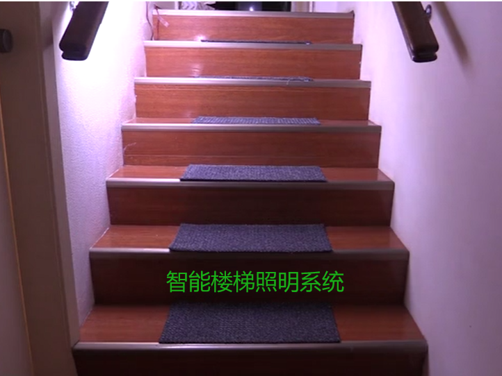
智能LED 楼梯照明系统

老小孩
转载
发布时间: 2025-06-14 15:43:42 | 阅读数 0收藏数 0评论数 0
封面
我为我们新家光线昏暗的楼梯搭建了一个基于Arduino的自动LED灯控制器。楼梯本来就很危险,尤其是在晚上,但现在有了Arduino的运动感应自动LED楼梯照明,一切都变好了。

准备工作:

材料:

您将需要以下部件

  1. 一个 Arduino。我用的是 Leonardo,不过其他的都可以。
  2. 一条 LED 灯带(图中未显示)。电压应为 12 伏或更低,因为 Arduino 还将通过 Arduino 的外部电源插孔由 LED 灯带的电源供电。我的灯带长约 1.4 米,开启时电流约为 0.5 安。
  3. 一个 1 AMP 12-V DC 电源,带有 2.1 毫米桶形插孔,适合插入您的 Arduino。
  4. 一个N沟道MOSFET。我用的是IRF-1405,也试过IRF540N。两个都工作正常。也有人建议我,这个MOSFET不是这个项目的最佳选择(虽然对我来说确实有效),以下是更好的选择:IRLB8721、AOT240L、AO3400、IRLHM630、TSM2537CQ。我没有测试过这些MOSFET,很想听听任何尝试过的人的意见。
  5. 一个(或多个)PIR 运动探测器(我的是 HC-SR501 PIR)。
  6. 一个 LDR(光检测电阻)光电探测器
  7. 一个 10K 电阻器(棕色、黑色、黑色、红色和任何其他颜色)
  8. 一个 470 欧姆电阻器(黄色、紫色、黑色、黑色和任何其他颜色)
  9. 一块面包板
  10. 连接线。

如果您希望进行更永久的设置,那么我建议您从上面的列表中获取第二套第 1 至第 8 部分 - 另外:

  1. 一块原型板
  2. 连接组件的电线
  3. 一个 2 路螺丝接线端子(用于连接 LED 灯带)
  4. 一个 3 针接头(用于连接 PIR)。
  5. 焊料和烙铁

第二套零件并非绝对必要,但就我的情况而言,我觉得最好有两套项目配置。一套连接到我的电脑,这样我就可以测试程序的修改。一旦我对所做的任何更改感到满意,我就可以将更新后的代码上传到安装在楼梯上的设备上。

或者,在初始测试时,您可以考虑不使用 12 伏电源。在这种情况下,只需暂时用单个 LED + 470 欧姆电阻替换 MOSFET 和 LED 灯带即可。项目运行后,只需将 470 欧姆电阻 + LED 替换为 MOSFET + LED 灯带即可。

1

我家的环境

我刚搬家了,我家的入口/通道光线很差,所以这东西对我们新家来说是个不错的补充。另外,我们打算把它装到父母家,当作夜灯,方便半夜去卫生间。

鉴于上述情况以及至少一个请求,我更新了代码以支持多个 PIR 传感器。这些变化相对较小,我将在下面简要介绍。

通过仔细定位 LED 和 PIR 传感器,该项目可以轻松适应:

  1. 婴儿房夜灯 - LED 灯位于婴儿床下方,PIR 灯面向房门。如果您晚上不想开灯(或者您抱着宝宝),这款灯就特别方便。
  2. 老年人礼仪灯
  3. 夜间回家灯——将LED灯安装在入口大厅,传感器朝向大门。打开前门时,LED灯会自动亮起。
  4. 一盏安全灯。通过添加WiFi模块,您可以让它报告灯亮起的时间和/或检测到运动的时间。在计算机上捕获数据并根据需要进行分析。
  5. 许多其他场景需要自动照明(或带有 WiFi 模块)远程监控和/或控制。

这个相对简单的项目使用 PIR 运动传感器来检测靠近楼梯的人(和猫)。当它检测到有人靠近时,LED 灯带就会亮起。LED 灯带通过 MOSFET 控制,并具有相当酷炫的“渐亮”和“渐灭”效果。该项目演示了如何使用 Arduino 的一个 5 伏数字引脚控制 1 安培 12 伏的电源。最后,还有一个光照传感器,用于确保仅在光线足够暗时才打开 LED。

Arduino 控制程序(草图)采用一种称为“协作式多任务”的多任务处理方式。这使我能够控制 LED 的亮灭,同时通过 PIR 运动检测器检测运动并报告光照水平。其附加价值在于,在关闭灯光的同时检测新的运动,然后简单地将其再次亮起相对简单,无需过多复杂操作。这种协作式多任务处理技术适用于任何需要同时独立运行的项目。

Arduino 源代码也可以从GitHub帐户获取:

https://github.com/gm310509/Arduino/tree/master/Household/StairLight/StairLight


如果您发现我的项目有帮助,请考虑给我 买杯咖啡来支持我


2

连接所有东西

把这些部件连接在一起相对简单。除了电源连接外,电路主要分为三个部分:

  1. PIR 运动探测器(Arduino 上的引脚 2 以及根据需要的其他引脚)
  2. LDR 光照水平传感器(Arduino 上的引脚 A0)
  3. LED 控制(Arduino 上的引脚 3)

重要提示: LED 灯带由 12V 电源供电。该电源将从 Arduino 的 VIN 引脚获取。务必小心,切勿将12V 电源连接到任何其他 Arduino 引脚。如果您未能将 12V 电源与其他引脚隔离,则驱动电子设备工作的“魔法烟雾”可能会逸出。如果“魔法烟雾”逸出,您的 Arduino 可能无法继续工作,甚至可能损坏通过 USB 连接的计算机。

注意: LED 灯带通常为 12 伏。Arduino 无法直接提供足够的电源(电压或电流)来点亮 LED 灯带。初始测试时,您可以移除 12 伏灯带和 MOSFET,只需在引脚 3 和地之间连接一个带有 470 欧姆电阻的 LED 即可。

按照上方接线图或以下说明连接您的组件。电线颜色与上方接线图相对应。

电源连接:

  1. 12V 电源 (VIN) 连接至面包板上的一条电源轨(红线)
  2. 5V 电源 (5V) 连接至面包板上的另一个电源轨(橙色线)
  3. 将接地 (GND) 连接到面包板上的一条接地轨(黑线)
  4. 将面包板上的两个接地轨连接在一起(黑线)

光照度传感器:

  1. 插入您的 LDR 和 10K 电阻器(棕色、黑色、黑色、红色),以便 LDR 的一根引线连接到电阻器的一根引线。
  2. 将 LDR 和电阻的连接点连接到 arduino 上的 A0(灰线)
  3. 将 LDR 的另一端连接到接地轨
  4. 将 10K 电阻的另一端连接到 5V 导轨(橙色线)

安装 LDR 时,请确保其朝向楼梯间。如果朝向不同,它可能会检测到来自其他位置、未进入楼梯间的环境光。在这种情况下,由于传感器附近环境光较强,即使楼梯间较暗,LED 灯也可能无法按预期亮起。

PIR运动探测器:

  1. 将 PIR 上的电源引脚连接到面包板上的 5V 导轨(橙色线)
  2. 将 PIR 上的接地引脚连接到面包板上的 GND 导轨(黑线)
  3. 将 PIR 上的信号引脚连接到 Arduino 上的引脚 2 (D2)(黄线)

确保 PIR 能够“看到”楼梯间区域,以便只有进入或朝向楼梯间的运动才会激活 LED。 正如开篇评论中提到的,我已更新代码,允许连接几乎任意数量的 PIR 运动探测器。只需将附加 PIR 模块上的信号(或输出)端口连接到 Arduino 上未使用的 DIO 引脚即可。

注意:您需要修改代码(下一步)来告诉程序您已将附加 PIR 模块连接到何处。

MOSFET和LED灯带

注意:这是 12 V 与 5 V 电压唯一交汇的环节。实际上,12 V 和 5 V 电压从未真正交汇,因为在 MOSFET 内部,5 V 信号(连接到 MOSFET 栅极)与电路的其余部分(即连接到 MOSFET 源极和漏极的 12 V 部分)是隔离的。这篇维基百科文章解释了 MOSFET 的基本工作原理,并展示了栅极与其他元件之间的绝缘层。

  1. 将 MOSFET 插入面包板。
  2. 将栅极引脚连接到 470 欧姆电阻。查看 MOSFET 的数据表,确定哪个引脚是栅极。 假设您使用的 MOSFET 与我相同,那么当您手持 MOSFET,使散热器朝上,且外壳上的字迹朝向您时,栅极引脚很可能是左侧的引脚。
  3. 将电阻的另一端连接到 Arduino 上的引脚 3(绿线)
  4. 将 MOSFET 的漏极(很可能是中间的引脚和散热器)连接到 LED 灯带的阴极(蓝线)
  5. 将 MOSFET 的源极(如上所述握住 MOSFET 时的右侧引脚)连接到 GND(黑线)
  6. 将 LED 灯带的阳极连接到 12V 导轨(红线)

检查您的连接

连接好所有部件后,稍事休息,然后仔细检查连接情况。记住,如果任何 12 伏(VIN 红线)与电路其他部分的连接出现错误,都可能会释放出“魔法烟雾”,这对你的 Arduino 来说非常不利。

3

代码

以下是完整程序。只需将其复制粘贴到 Arduino IDE 的新项目中即可。无需任何特殊库,因此无需下载任何其他内容。

注意:如果您使用多个 PIR,则需要修改以下代码中 pirPins 数组的定义(大约第 37 行)。请使用注释掉的代码示例来演示如何定义 2 个或 3 个 PIR 模块。如果您愿意,可以添加更多示例所示的 PIR 模块,只需确保更新 pirPins 数组定义即可。

如果您按照本说明的大部分内容所述将单个 PIR 连接到数字 IO 引脚 2,那么您可以按原样使用代码。

/******************************************************************************
* Automatic Stair light controller
*
* Detects motion via a PIR (pin 2 digital) and gradually turns on an LED Light strip (pin 3 digital).
* When motion ceases the LED light strip is gradually turned off.
*
* An LDR (Analog A0) is used to detect ambient light levels. The LED is only turned on if the ambient
* light level is lower than a specified threshold.
*
* Change history
* --------------
* 2020-10 GMc Added Debug constant+debug messages
* Expanded the PIR checking to support multiple PIR's
*
* 2016-04 GMc Initial Version
*/

// Uncomment the following for debug messages.
//#define DEBUG

// Define a constant that determines at what light level should
// should the LED strip be turned on. If the light level is above
// this threshold, the LED strip will not be turned on when motion is triggered.
#ifdef DEBUG
#define LIGHT_ON_THRESHOLD 700
#else
#define LIGHT_ON_THRESHOLD 200
#endif


// The pins to which the various peripherals are connected.
// NB: The pirPins array defines the pins to which the PIR signal (or out) pins are connected to.
// IMPORTANT: The contents of this array need to be modified to reflect the number of PIR's that you have.
// each entry in the pirPins array defines that a PIR is connected to the specified pin.
// below are three examples that show 1 to 3 PIRs connected to the Arduino.

const int pirPins [] = {2}; // Define a single PIR connected to DIO pin 2
//const int pirPins [] = {2, 4}; // Define dual PIRs. One is connected to DIO pin 2, the other to DIO pin 4.
//const int pirPins [] = {2, 4, 5}; // Define triple PIRs. They are connected to DIO pins 2, 4 and 5.

const int pirCount = sizeof(pirPins) / sizeof(pirPins[0]); // The number of PIR's defined.
const int ledStripPin = 3; // Output: PWM signal to the MOSFET.
const int lightSensorPin = A0; // Input: The reading from the ligh sensor (LDR)


// Cooperative multi-tasking data.
// Cooperative multi-tasking works by activating a task from time to time.
// The period of time between activations depends upon the task.
// This variables is used to track the point in time that we last checked the
// Arduino clock. Our main loop will continually check to see if the Arduino's clock
// has ticked over (> 1ms has passed since we last did anything). If it has, then
// the individual tasks are checked to see if it is time that they should be activated.
//
// You can visually see this working if you activate the Serial monitor in the Arduino IDE.
// What you will see is that the ambient light level reporting will seemingly randomly appear
// in amongst any other debugging messages you might add to the program (e.g. outputting the
// brightness level during a fade).
//
unsigned long timePrev = 0;

// Multi-tasking sub tasks:
// - Read the PIR once every 10 ms.
// - If turning on the LED's, adjust the brightness ever 10 ms
// - It turning off the LED's, adjust the brightness every 30 ms
// - Report the light leveel once every second (this is primarily for testing).
#define PIR_TIME 10 // Check the PIR every 10 ms
unsigned int pirReadTmr = 0; // A counter to measure how long since we last checked the PIR

#define FADE_ON_TIME 10 // LED's "fade on", the brightness is increased every 10 ms.
#define FADE_OFF_TIME 30 // LED's "fade off", the brightness is decreased every 30 ms.
unsigned int faderTime = FADE_ON_TIME; // will be set to either FADE_ON_TIME or FADE_OFF_TIME depending upon
// whether we are turning the LED's on or off.
unsigned int faderDelayTmr = 0; // A counter to measure how long since we last adjusted the LED brightness.

#define LIGHT_CHECK_TIME 1000 // Check the ambient light level once every 1000 ms (once per second)
unsigned int lightCheckTmr = 0; // A counter to measure how long since we last reported the ambient light level.

/*****************************************************************************
* Setup:
* - Initialise the Serial comm's just in case we are debugging/testing.
* - set up the MOSFET (ledStripPin) and builtin LED PIN to output
* - Initialise the multi-tasking timer (timePrev),
*/
void setup() {

Serial.begin(115200);
int cnt = 0;
// Wait for the the Serial port to initialise (but don't wait forever)
while (!Serial && cnt < 100) {
cnt++;
delay(10);
}
// Set the digital outputs (LED_BUILTIN and LED Strip MOSFET)
pinMode(LED_BUILTIN, OUTPUT);
digitalWrite(LED_BUILTIN, LOW);
pinMode(ledStripPin, OUTPUT);

#ifdef DEBUG
Serial.println(F("Debug mode on"));
#endif
Serial.println(F("Ready"));

// Initialise the time Keeper
timePrev = millis();
}

/*****************************************************************************
* Loop:
* - Check to see if the time has changed.
* - If the time has changed, work out how long has elapsed since the last
* time we checked (should always be 1 ms)
* - Update the 3 sub-task time counters.
* - Check each sub-task time counter to see if it has passed it's respective
* threshold.
* - If we have passed the threshold, call the appropriate sub-task.
* - reset the appropriate time counter to 0.
*/
void loop() {

// Get the current time in millis.
// Note that the value is unsigned long. If you do not use unsigned long, then
// after a few days your multi-tasking might "freak out" (the technical term for
// not performing as expected).
unsigned long timeNow = millis();

// Has the time progressed since last time we checked?
if (timeNow != timePrev) {
// Yep, so work out how long has passed (normally 1 ms)
unsigned int delta = timeNow - timePrev;
// Capture the current time so we can check if time has moved on from "right now".
timePrev = timeNow;

// Update the sub-task time counters.
pirReadTmr += delta;
faderDelayTmr += delta;
lightCheckTmr += delta;

// Has the pir timer passed it's threshold? If so, check the PIR.
if (pirReadTmr >= PIR_TIME) {
processPir();
pirReadTmr = 0;
}

// Has the fader timer passed it's threshold? If so, adjust the brightness of the LED's
if (faderDelayTmr >= faderTime) {
processFade();
faderDelayTmr = 0;
}

// Has the ambient light level timer passed it's threshold? If so, report the ambient light level.
if (lightCheckTmr >= LIGHT_CHECK_TIME) {
processLightCheck();
lightCheckTmr = 0;
}
}
}

/*******************************************************
* check PIR Array
* Check each of the PIRs for motion detection.
* If any of them report motion detected, return a HIGH value (motion detected).
* Otherwise if none of them have reported any motion detected (i.e. all of them are LOW), then return a LOW value.
*/
int checkPirArray() {
// Step through the array of PIRs one by one
for (int i = 0; i < pirCount; i++) {
int triggeredInd = digitalRead(pirPins[i]); // Read the PIR
if (triggeredInd) { // Is it triggered (i.e. triggeredInd is HIGH)?
#ifdef DEBUG
Serial.print("pir "); Serial.print(i); Serial.print(F(" (DIO pin ")); Serial.print(pirPins[i]); Serial.println(F(") triggered."));
#endif
return HIGH; // Yes, it is triggered, we only need one, so return immediately with a "motion detected" status.
}
}
return LOW; // None of the PIRs are triggered, so return a no motion detected status.
}

/*****************************************************************************
* Multi-tasking
4

测试

一旦您对 Arduino 进行了编程并连接好了所有东西,就该进行一些测试了。

如果将 Arduino 连接到您的计算机并且您在 Arduino IDE 中的串行监视器上监视调试消息,则测试最简单。

如果您像我一样对连接 12 伏电源感到紧张,可以直接将 12 伏电源和 MOSFET 放在电路之外。只需在 PIN 3 和地之间连接一个 LED 和 470 欧姆电阻即可。

运行后,尝试在 PIR 前挥动手。您应该会看到:

  1. 串行监视器中显示一条消息,表明已检测到移动。
  2. Arduino 的内置 LED 应该亮起。
  3. 如果光读数低于阈值,您的 LED 灯带(或测试 LED)应该“淡亮”。

等待一会儿,不要移动。几秒钟后,你应该会看到:

  1. 串行监视器中显示一条消息,表明移动已停止。
  2. Arduino 的内置 LED 应该关闭。
  3. LED 灯带(或测试 LED)应该“熄灭”。

故障排除

尝试通过取消注释程序顶部附近的行“#define DEBUG”来打开 DEBUG 模式。

如果您看到消息并且内置 LED 亮起/熄灭,但 LED 灯带(或测试 LED)未亮,则:

  1. 仔细检查所有连接。
  2. 检查测试 LED/LED 灯带的方向。阳极(通常是红线)连接到正极电源。阴极(通常是黑线)连接到 MOSFET 的漏极。
  3. 确保报告的环境光水平低于 Arduino 程序常量中设置的阈值:LIGHT_ON_THRESHOLD。

提示:您可以用手指或卡片遮盖光敏电阻,人为地降低环境光亮度。如果您启用调试功能,“亮灯阈值”将自动调整为更高的值。

如果似乎没有发生任何事情(没有检测到运动/停止消息):

  1. 仔细检查所有连接。
  2. 确保 PIR 正确连接(信号转到 Arduino 上的 PIN 2)。
  3. 尝试调整灵敏度。我的PIR上有两个螺丝可变电阻,分别标有Sx和Tx。Sx是灵敏度。尝试将其调到任意极端。我的灵敏度调到中间值时效果最佳。

您会看到检测到运动的消息,但永远不会看到运动停止的消息:

  1. 仔细检查所有连接。
  2. 等待运动检测停止时,请确保您(以及附近的任何人——包括您的猫,如果您养了猫的话)保持静止(尝试遮住 PIR)。即使在很远的距离内,PIR 对最轻微的运动也非常敏感。
  3. 检查 PIR 上的 Tx 设置。Tx 是 PIR 报告运动停止之前的延迟时间。在我的设备上,最佳设置是完全逆时针旋转(延迟最小)。

如果您使用了单个测试 LED(即没有 MOSFET 且电压不是 12 伏),那么一旦您确信它工作正常:

  1. 仔细检查所有连接
  2. 移除测试 LED 和 470 欧姆电阻器。
  3. 按照上面的接线说明连接 MOSFET 和 LED 灯带。
  4. 仔细检查所有连接。
  5. 插入 12 伏电源。
  6. 欣赏你的杰作。
5

安装

安装将取决于您的楼梯的设计。

我家只有一条木扶手。我直接把LED灯带粘在楼梯扶手下面。我的LED灯带背面有胶,但不足以把LED灯带固定在木扶手上(即使我事先彻底清洁了扶手)。最后,我干脆用1毫米厚的双面胶粘在扶手上,再把LED灯带粘在双面胶上。

我在Arduino原型开发板上制作了第二个电路副本。它和第二个Arduino一起安装在靠近楼梯顶部入口的地方。目前,Arduino和传感器只是放在地板上靠墙的位置。用双面胶将PIR传感器固定在门框上。PIR传感器朝下朝向楼梯间,可以检测楼梯顶部和底部的运动。PIR传感器通过一些跳线连接到Arduino原型开发板。图片展示了我完成的装置,其中有两组连接PIR传感器和LED灯带的线缆。

阅读记录0
点赞0
收藏0
禁止 本文未经作者允许授权,禁止转载
猜你喜欢
评论/提问(已发布 0 条)
评论 评论
收藏 收藏
分享 分享
pdf下载 下载