纸牌习惯追踪器
发布时间: 2025-06-14 15:13:07 |  0
0 0
0 0
0 0
0
0Arduino
纸牌
习惯追踪器
Arduino
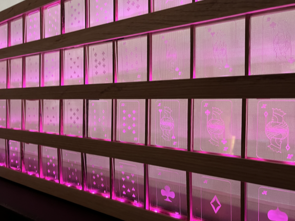
有没有想过一副纸牌是日历?做好这一个项目大约需要2个月的时间。我以这副卡片作为我们的指南(52张卡片=52天),我使用Arduino创建了这个视觉日历来追踪我在生活中试图实现的新的健康习惯.
准备工作:
材料:
一副纸牌
亚克力板(18x24 英寸和 3/16 英寸厚)
框架木材
Perma Proto 面包板
独立的瞬时电容式触摸传感器分线
Stranded Wire
烙铁
焊料
剪线钳
螺丝
LED 灯带
1
设计您的纸牌

对于这个项目,我想从头开始设计我的纸牌,所以我制作了自己的插图。这些插图将被激光切割和雕刻,以制作视觉追踪器的视觉元素。
激光切割时,每个亚克力板的尺寸为 2.5 x 3 英寸。亚克力板的大小取决于 LED 灯条的类型。在这种情况下,尺寸基于我的 LED 灯条,即 30 像素。
2
激光切割和雕刻

雕刻所有插图和激光切割边框以适应精确的尺寸。(2.5 x 3 英寸)
3
构建框架

根据 LED 灯条的测量值构建框架。
在我的情况下,它是每个图块 2 个像素,每行 13 个图块,即每行 26 个像素,共有 4 行。
我的店铺里没有状况良好的木板,所以我不得不即兴创作并使用普通的台锯片来制作我的框架。
我必须通过毫米逐渐增加切割叠加来制作我的导轨,以使其紧贴 LED 灯条。
每个栏杆的顶部和底部都有一个通道,用于存放亚克力板。
4
焊接

将 LED 灯条焊接在一起,确保您有足够的电线缠绕在导轨上并到达另一侧。
电缆管理是关键。
5
代码

#include <Adafruit_NeoPixel.h>
// Which pin on the Arduino is connected to the NeoPixels?
// On a Trinket or Gemma we suggest changing this to 1:
#define LED_PIN 6
// How many NeoPixels are attached to the Arduino?
#define LED_COUNT 200
// this constant won't change:
const int buttonPin = 2; // the pin that the pushbutton is attached to
// Variables will change:
int buttonPushCounter = 0; // counter for the number of button presses
int buttonState = 0; // current state of the button
int lastButtonState = 0; // previous state of the button
// Declare our NeoPixel strip object:
Adafruit_NeoPixel strip(LED_COUNT, LED_PIN, NEO_GRB + NEO_KHZ800);
// Argument 1 = Number of pixels in NeoPixel strip
// Argument 2 = Arduino pin number (most are valid)
// Argument 3 = Pixel type flags, add together as needed:
// NEO_KHZ800 800 KHz bitstream (most NeoPixel products w/WS2812 LEDs)
// NEO_KHZ400 400 KHz (classic 'v1' (not v2) FLORA pixels, WS2811 drivers)
// NEO_GRB Pixels are wired for GRB bitstream (most NeoPixel products)
// NEO_RGB Pixels are wired for RGB bitstream (v1 FLORA pixels, not v2)
// NEO_RGBW Pixels are wired for RGBW bitstream (NeoPixel RGBW products)
void setup () {
Serial.begin(57600);
strip.begin(); // INITIALIZE NeoPixel strip object (REQUIRED)
strip.show(); // Turn OFF all pixels ASAP
strip.setBrightness(50); // Set BRIGHTNESS to about 1/5 (max = 255)
// initialize the button pin as a input:
pinMode(buttonPin, INPUT);
#ifndef ESP8266
while (!Serial); // wait for serial port to connect. Needed for native USB
#endif
}
void loop () {
// read the pushbutton input pin:
buttonState = digitalRead(buttonPin);
// compare the buttonState to its previous state
if (buttonState != lastButtonState) {
// if the state has changed, increment the counter
if (buttonState == HIGH ) {
// if the current state is HIGH then the button went from off to on:
Serial.println("on");
Serial.print("number of button pushes: ");
Serial.println("count"+buttonPushCounter);
strip.setPixelColor(buttonPushCounter, strip.Color(255, 0, 203));
strip.setPixelColor(buttonPushCounter+1, strip.Color(255, 0, 203)); // Set pixel's color (in RAM)
//strip.setPixelColor(buttonPushCounter+1, strip.Color(255, 255, 0)); // Set pixel's color (in RAM)
strip.show(); // Update strip to match
buttonPushCounter=buttonPushCounter+2;
Serial.println(buttonPushCounter);
lastButtonState++;
Serial.println(lastButtonState);
} else {
// if the current state is LOW then the button went from on to off:
//Serial.println("off");
}
// Delay a little bit to avoid bouncing
delay(50);
}
lastButtonState = buttonState;
delay(150);
}
6
组装

在确保你的代码和部分都协同工作之后,是时候将它们全部组装起来了。
我用 自攻丝和木胶来做框架角。
钻出导向孔,用于使用螺钉将导轨连接到框架上。
每块亚克力板都有一个细长的木质隔板,以确保每块亚克力板都保持在原位,并且光线正确扩散。
 0
0 0
0 0
0 qq空间
qq空间  微博
微博  复制链接
复制链接 更多相关项目
猜你喜欢
评论/提问(已发布 0 条)