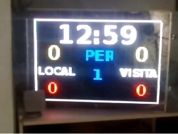
发光板 Pi

老小孩
转载
发布时间: 2025-06-14 15:35:41 | 阅读数 0收藏数 0评论数 0
封面
Ledboard Pi屏幕由任何计算机控制,能够运行VNC Viewer,因为VNC 服务器也安装在 Raspberry Pi 4 的 Rasbian Buster Lite 上。

准备工作:

材料:

硬件

  1. 一台 Raspberry Pi 3 或更高版本,Raspberry Pi 4 及其 5V 2.5 A 电源
  2. 一块适用于 Raspberry Pi 的 Electrodragon RGB LED 矩阵面板驱动板
  3. Sparkfun 的六个32x32 RGB LED 面板
  4. 一个40A 5V电源
  5. 一个3 米铝制矩形框架 82.5 毫米 x 38 毫米
  6. 一块亚克力切割件,尺寸为宽 576 毫米 x 高 384 毫米
  7. 一片偏光膜

软件

  1. hezeller rpi-rgb-led-matrix
  2. Adafruit rpi-fb-matrix
  3. Raspbian buster literealtimepi-buster-lite 图像
  4. 开放盒子
  5. 用于控制 PC/笔记本电脑/Raspberry Pi 3 或 4,适用于WindowsLinuxRaspbian 的Real VNC Viewer
  6. 适用于 raspbian buster lite 的 Lazarus IDE
  7. Leboard Pi 应用程序
1

设置 Raspberry Pi 3/4 操作系统

一旦我们有了硬件部件,我们就需要获取操作系统部件:

首先,我们必须获取适用于 Raspbian 3/4 的操作系统。就我而言,我决定使用实时 buster lite;但您也可以使用Raspbian Buster Lite 版本。然后您需要使用 balenaEtcher将此图像传输到 micro SD卡中。

然后,我们需要连接一个 HDMI 显示器和一个 USB 键盘以及一条连接到

Raspberry Pi 3/4 RJ45;因此,我们可以搜索 Raspberry Pi 3/4 IP 以进行初始设置:网络 IP、有线和无线。我使用了高级 IP 扫描器。现在,通过 raspi-config,激活 SSH 服务器以使用Putty进行远程连接,以完成 Ledboard Pi 设置的其余部分。

现在,在精简版上,我们将使用 openbox 安装一个精简桌面环境

sudo apt-get install --no-install-recommends xserver-xorg x11-xserver-utils xinit openbox

然后,安装lightdm(登录管理器)

sudo apt-get install lightdm

从 raspi-config激活realvncserver

sudo raspi-config > Interface options > vncserver > activate vncserver

在这里,一旦激活了 vnceserver,我们将使用 VNC Viewer。在这里,连接中要配置的桌面是 0,例如,如果 IP 是 192.168.100.61,则连接为“192.168.100.61:0”。

我们需要控制计算机/笔记本电脑和Ledboard Pi之间的连接,因此需要安装samba来传输源代码、文件、图片、视频等。

sudo apt-get install samba samba-common-bin -y

确保您的用户是您尝试通过 Samba 共享的路径的所有者

sudo chown -R pi:pi /home/pi/share

复制原始 samba 共享文件

sudo cp /etc/samba/smb.conf /etc/samba/smb.bak

编辑 samba 配置文件

sudo nano /etc/samba/smb.conf

将工作组保留为 WORKGROUP(或按您的意愿命名)

#wins support = no
to
wins support = yes

然后 ....

#This is the name of the share folder it will show up as when you browse
[ledboardpi]
comment = ledboardPi share folder
path = /home/pi/Share
create mask = 0775
directory mask = 0775
read only = no
browseable = yes
public = yes
force user = pi
only guest = no

现在,我们可以从其他计算机访问 /home/pi 路径中的“home/pi/share”文件夹。

为了使用 GUI 应用程序管理文件系统,我们将安装 pcmanfm

sudo apt-get install pcmanfm


2

下载、设置和运行 RGB LED 面板所需库

首先,安装先决条件

sudo apt-get update

sudo apt-get install -y build-essential git libconfig++-dev
sudo apt-get install libgraphicsmagick++-dev libwebp-dev -y
sudo apt-get install python2.7-dev python-pillow -y
  1. 然后,下载并编译 hzeller rpi-rgb-led-matrix
wget https://github.com/hzeller/rpi-rgb-led-matrix/archive/master.zip
unzip master.zip
cd rpi-rgb-led-matrix-master/ && make
  1. 另外,下载并安装 rpi-fb-matrix

您必须使用递归选项克隆此存储库,以便必要的子模块也被克隆。运行以下命令:

git clone --recursive https://github.com/adafruit/rpi-fb-matrix.git
make

注意:将之前下载的rpi-rgb-led-matrix库替换到rpi-fb-matrix文件夹中

  1. 现在,我们将测试这些库,记住,rpi-fb-matrix 依赖于 rpi-rgb-led-matrix。
cd rpi-fb-matrix
cd rpi-rgb-led-matrix
sudo ./demo --led-chain=3 --led-parallel=2 --led-slowdown-gpio=4 --led-gpio-mapping="regular" --led-no-hardware-pulse --led-pwm-lsb-nanoseconds=180 --led-show-refresh --led-brightness=80 -D 0
sudo ./demo --led-chain=3 --led-parallel=2 --led-slowdown-gpio=4 --led-gpio-mapping="regular" --led-no-hardware-pulse --led-pwm-lsb-nanoseconds=180 --led-show-refresh --led-brightness=80 -D 1 runtext.ppm
sudo ./demo --led-chain=3 --led-parallel=2 --led-slowdown-gpio=4 --led-gpio-mapping="regular" --led-no-hardware-pulse --led-pwm-lsb-nanoseconds=180 --led-show-refresh --led-brightness=80 -D 2 runtext.ppm
sudo ./demo --led-chain=3 --led-parallel=2 --led-slowdown-gpio=4 --led-gpio-mapping="regular" --led-no-hardware-pulse --led-pwm-lsb-nanoseconds=180 --led-show-refresh --led-brightness=80 -D 3
sudo ./demo --led-chain=3 --led-parallel=2 --led-slowdown-gpio=4 --led-gpio-mapping="regular" --led-no-hardware-pulse --led-pwm-lsb-nanoseconds=180 --led-show-refresh --led-brightness=80 -D 4
sudo ./demo --led-chain=3 --led-parallel=2 --led-slowdown-gpio=4 --led-gpio-mapping="regular" --led-no-hardware-pulse --led-pwm-lsb-nanoseconds=180 --led-show-refresh --led-brightness=80 -D 5
sudo ./demo --led-chain=3 --led-parallel=2 --led-slowdown-gpio=4 --led-gpio-mapping="regular" --led-no-hardware-pulse --led-pwm-lsb-nanoseconds=180 --led-show-refresh --led-brightness=80 -D 6
sudo ./demo --led-chain=3 --led-parallel=2 --led-slowdown-gpio=4 --led-gpio-mapping="regular" --led-no-hardware-pulse --led-pwm-lsb-nanoseconds=180 --led-show-refresh --led-brightness=80 -D 7
sudo ./demo --led-chain=3 --led-parallel=2 --led-slowdown-gpio=4 --led-gpio-mapping="regular" --led-no-hardware-pulse --led-pwm-lsb-nanoseconds=180 --led-show-refresh --led-brightness=80 -D 8
sudo ./demo --led-chain=3 --led-parallel=2 --led-slowdown-gpio=4 --led-gpio-mapping="regular" --led-no-hardware-pulse --led-pwm-lsb-nanoseconds=180 --led-show-refresh --led-brightness=80 -D 9
sudo ./demo --led-chain=3 --led-parallel=2 --led-slowdown-gpio=4 --led-gpio-mapping="regular" --led-no-hardware-pulse --led-pwm-lsb-nanoseconds=180 --led-show-refresh --led-brightness=80 -D 10
sudo ./demo --led-chain=3 --led-parallel=2 --led-slowdown-gpio=4 --led-gpio-mapping="regular" --led-no-hardware-pulse --led-pwm-lsb-nanoseconds=180 --led-show-refresh --led-brightness=80 -D 11<br>

一切运行良好。

  1. 现在,rpi-fb-matrix 库。这将在基于 Ledboard Pi 的 RGB LED 面板中显示屏幕的一部分(96x64)
cd /home/pi/rpi-fb-matrix

请记住,将 rpi-rgb-led-matrix 库的最新版本复制到 rpi-fb-matrix 文件夹中。非常重要

make clean
make all

这些最后的命令,适用于 rpi-fb-matrix 和 rpi-rgb-led-matrix 库.....

对于 rpi-fb-matrix,需要正确配置 matrix.cfg(我为此指导重命名了 davenew.cfg),读取、分析具有不同数量 RGB LED 面板的定制项目...

LED Matrix Display Configuration<br>
// Define the entire width and height of the display in pixels.
// This is the _total_ width and height of the rectangle defined by all the
// chained panels. The width should be a multiple of the panel pixel width (32),
// and the height should be a multiple of the panel pixel height (8, 16, or 32).
display_width = 96;
display_height = 64;


// Define the width of each panel in pixels. This should always be 32 (but can
// in theory be changed).
panel_width = 32;


// Define the height of each panel in pixels. This is typically 8, 16, or 32.
// NOTE: Each panel in the display _must_ be the same height! You cannot mix
// 16 and 32 pixel high panels for example.
panel_height = 32;


// Define the total number of panels in each chain. Count up however many
// panels are connected together and put that value here. If you're using
// multiple parallel chains count each one up separately and pick the largest
// value for this configuration.
chain_length = 3;


// Define the total number of parallel chains. If using the Adafruit HAT you
// can only have one chain so stick with the value 1. The Pi 2 can support up
// to 3 parallel chains, see the rpi-rgb-led-matrix library for more information:
// https://github.com/hzeller/rpi-rgb-led-matrix#chaining-parallel-chains-and-coordinate-system
parallel_count = 2;


// Configure each LED matrix panel.
// This is a two-dimensional array with an entry for each panel. The array
// defines the grid that will subdivide the display, so for example a 64x64 size
// display with 32x32 pixel panels would be a 2x2 array of panel configurations.
//
// For each panel you must set the order that it is within its chain, i.e. the
// first panel in a chain is order = 0, the next one is order = 1, etc. You can
// also set a rotation for each panel to account for changes in panel orientation
// (like when 'snaking' a series of panels end to end for shorter wire runs).
//
// For example the configuration below defines this grid display of panels and
// their wiring (starting from the upper right panel and snaking left, down, and
// right to the bottom right panel):
// ______________ ______________ ______________
// | Panel | | Panel | | Panel |
// | order = 2 |<=| order = 1 |<=| order = 0 |<= Chain 1 (from Pi)
// | rotate = 0 | | rotate = 0 | | rotate = 0 |
// |______________| |______________| |______________|
// ______________ ______________ ______________
// | Panel | | Panel | | Panel |
// | order = 2 |<=| order = 1 |<=| order = 0 |<= Chain 2 (from Pi)
// | rotate = 0 | | rotate = 0 | | rotate = 0 |
// |______________| |______________| |______________|
//
// Notice the chain starts in the upper right and snakes around to the bottom
// right. The order of each panel is set as its position along the chain,
// and rotation is applied to the lower panels that are flipped around relative
// to the panels above them.
//
// Not shown but if you're using parallel chains you can specify for each entry
// in the panels list a 'parallel = x;' option where x is the ID of a parallel
// chain (0, 1, or 2).
panels = ( ( { order = 2; rotate = 0; parallel=0; }, { order = 1; rotate = 0; parallel=0;} , { order = 0; rotate = 0; parallel=0;},
{ order = 2; rotate = 0; parallel=1; }, { order = 1; rotate = 0; parallel=1;} , { order = 0; rotate = 0; parallel=1;} )
)

// By default the rpi-fb-matrix tool will resize and scale down the screen
// to fit the resolution of the display panels. However you can instead grab
// a specific pixel-perfect copy of a region of the screen by setting the x, y
// screen pixel coordinates below. A rectangle of the exact size of the display
// (i.e. display_width x display_height pixels) will be copied from the screen
// starting at the provided x, y coordinates. Comment this out to disable
// this crop behavior and instead resize the screen down to the matrix display.
crop_origin = (0, 0)
3

编译、设置和测试 Ledboard Pi GUI 应用程序

  1. 我们需要一个编程 IDE 来创建 GUI 应用程序 (Ledboard Pi)。然后,我选择“Lazarus IDE”,它与我在 Windows 操作系统中使用的 Delphi/C++ Builder 非常相似。
sudo apt-get install lazarus-ide
  1. 安装后,只需执行:
lazarus-ide
  1. 打开 Ledboard Pi 项目,然后编译以获取Ledboard Pi 应用程序。打开此应用程序之前,在路径 /home/pi 中创建一个名为 LEDBOARD_APP 的目录,然后将 Ledboard Pi 应用程序复制到此目录中。
  2. 现在,我们要在 openbox 的右键菜单中添加一个链接。我们需要 obmenu,也需要 xterm 使用 Putty 链接,因此:
sudo apt-get install obmenu xterm
  1. 现在,我们可以在 vncviewer 窗口中使用终端和菜单:
  2. 从右键菜单调用 xterm
  3. 从 xterm 打开 obmenu
  4. 添加新项目:Ledboard Pi
  5. 选择新商品
  6. 将其命名为 Ledboard Pi
  7. 执行 sudo nice -n -15 /home/pi/LEDBOARD_APP/LEDBOARD
  8. 下载“ horn.WAV ”,然后使用网络连接的 samba 位置“\\ledboardpi\ledboardpi\”复制此文件并将其重命名为“horn.wav”,放入 realtimePi 环境中。重命名后,必须将此文件复制到 /home/pi 文件夹。
  9. 完成后,您必须能够运行 Ledboard Pi,就像您在视频和图片中看到的那样。
4

安装和设置 WiFi 热点

该项目设计为使用 realvnc viewer 从无线连接到 Raspberry Pi 3/4 的笔记本电脑运行。所以,这是让它运行的最后一步,对有线噩梦说“hasta la vista baby”吧。

软件设置

sudo apt-get update
sudo apt-get install hostapd isc-dhcp-server

DHCP 服务器

  1. 明智一点,始终备份默认配置
sudo cp /etc/dhcp/dhcpd.conf /etc/dhcp/dhcpd.conf.default
  1. 编辑默认配置文件
sudo nano /etc/dhcp/dhcpd.conf
  1. 注释以下几行...
option domain-name "example.org";
option domain-name-servers ns1.example.org, ns2.example.org;
  1. 阅读:
#option domain-name "example.org";
#option domain-name-servers ns1.example.org, ns2.example.org;
  1. ...并取消注释此行
#authoritative;
  1. ...阅读:
authoritative;
  1. ... 向下滚动文件底部并写入以下行:
subnet 192.168.42.0 netmask 255.255.255.0 {
range 192.168.42.10 192.168.42.50;
option broadcast-address 192.168.42.255;
option routers 192.168.42.1;
default-lease-time 600;
max-lease-time 7200;
option domain-name "local";
option domain-name-servers 8.8.8.8, 8.8.4.4;
}

让我们将 wlan0 设置为静态 IP

  1. 首先,将其关闭...
sudo ifdown wlan0
  1. ...保持安全并制作备份文件:
sudo cp /etc/network/interfaces /etc/network/interfaces.backup
  1. ...编辑网络接口文件:
sudo nano /etc/network/interfaces
  1. ... 相应编辑如下:
source-directory /etc/network/interfaces.d

auto lo

iface lo inet loopback
iface eth0 inet dhcp

allow-hotplug wlan0

iface wlan0 inet static
address 192.168.42.1
netmask 255.255.255.0
post-up iw dev $IFACE set power_save off
  1. ...关闭文件并立即分配静态 IP
sudo ifconfig wlan0 192.168.42.1

完毕...

主机

  1. 创建文件并编辑:
sudo nano /etc/hostapd/hostapd.conf
  1. 将 ssid 修改为您选择的名称,并将 wpa_passphrase 修改为 WiFi 身份验证
interface=wlan0
ssid=LedboardPi
hw_mode=g
channel=6
macaddr_acl=0
auth_algs=1
ignore_broadcast_ssid=0
wpa=2
wpa_passphrase=davewarePi
wpa_key_mgmt=WPA-PSK
wpa_pairwise=TKIP
rsn_pairwise=CCMP

让我们配置网络地址转换

  1. 创建备份文件
sudo cp /etc/sysctl.conf /etc/sysctl.conf.backup
  1. 编辑配置文件
sudo nano /etc/sysctl.conf
  1. ...取消注释或者添加到底部:
net.ipv4.ip_forward=1
  1. #...并立即激活它:
sudo sh -c“echo 1> /proc/sys/net/ipv4/ip_forward”
  1. ...修改 iptables 以在 eth0 和 wifi 端口 wlan0 之间创建网络转换
sudo iptables -t nat -A POSTROUTING -o eth0 -j MASQUERADE
sudo iptables -A FORWARD -i eth0 -o wlan0 -m state --state RELATED,ESTABLISHED -j ACCEPT
sudo iptables -A FORWARD -i wlan0 -o eth0 -j ACCEPT
  1. ...通过运行使此操作在重启时发生
sudo sh -c “iptables-save > /etc/iptables.ipv4.nat”
  1. ...并再次编辑
sudo nano /etc/network/interfaces
  1. ...附加到结尾:
up iptables-restore < /etc/iptables.ipv4.nat
  1. 我们的 /etc/network/interfaces 文件现在看起来像这样:
source-directory /etc/network/interfaces.d
auto lo

iface lo inet loopback

allow-hotplug eth0

iface eth0 inet static
address 192.168.100.61
netmask 255.255.255.0
gateway 192.168.100.1

allow-hotplug wlan0

iface wlan0 inet static
address 192.168.42.1
netmask 255.255.255.0
network 192.168.42.0
broadcast 192.168.42.255

source-directory /etc/network/interfaces.d

让我们通过运行以下命令来测试我们的接入点:

sudo /usr/sbin/hostapd /etc/hostapd/hostapd.conf
  1. 您的热点已启动并运行:尝试从计算机或智能手机连接到它。当您这样做时,您还应该在终端上看到一些日志活动。如果您满意,请使用 CTRL+C 停止它
  2. 让我们清理一切: sudo service hostapd start sudo service isc-dhcp-server start
  3. ...并确保我们已启动并运行:
sudo service hostapd status
sudo service isc-dhcp-server status
  1. ...让我们配置我们的守护进程在启动时启动:
sudo update-rc.d hostapd enable
sudo update-rc.d isc-dhcp-server enable

sudo systemctl unmask hostapd
sudo systemctl unmask isc-dhcp-server
  1. ...重新启动 pi。
sudo reboot

现在您应该能够看到您的 pi WiFi,连接到它并访问互联网。作为快速比较,流式传输 4k 视频将消耗大约 10% 的 pi CPU,因此……请相应地使用它。

另外,如果您想检查 WiFi 热点上发生的情况,请检查日志文件:

tail -f /var/log/syslog
5

设计

案件。

设计

对于这部分,我使用了 Sketchup 3D 设计程序。Ledboard Pi 铝制外壳 3D 设计

为此,我使用了常见的矩形 82.5 毫米 x 38 毫米铝型材、一些角和一些螺丝。支架是我妈妈在街上建立的,浪费了。它有轮子,如图所示。

阅读记录0
点赞0
收藏0
禁止 本文未经作者允许授权,禁止转载
猜你喜欢
评论/提问(已发布 0 条)
评论 评论
收藏 收藏
分享 分享
pdf下载 下载